 Juchip Semiconductor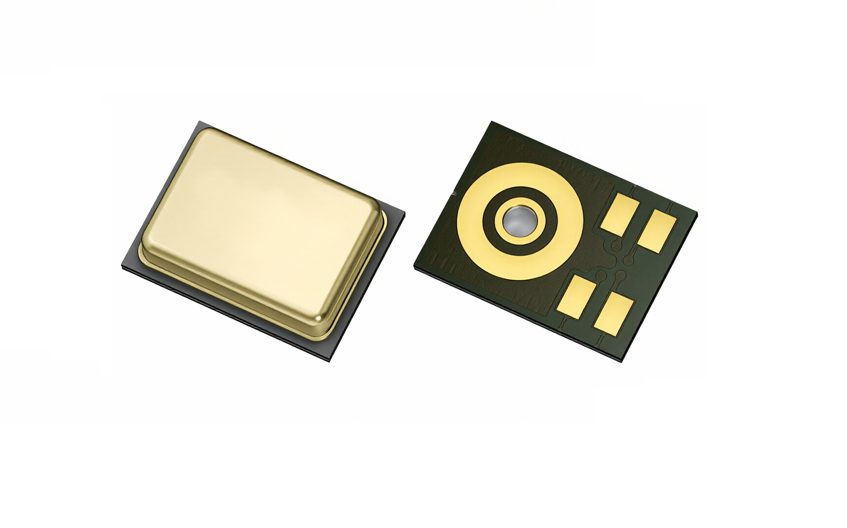
Digital PDM MEMS Microphone (ECM Replacement)
JSM3526DB26UJ0
Digital PDM MEMS Microphone (ECM Replacement)3.5×2.65×0.98mm · Bottom-port
A bottom-ported digital silicon microphone: a MEMS sensor plus encoder IC converts the analog output to a 1-bit PDM stream — eliminating AC coupling, reducing RF noise coupling and easing PCB layout. A cost-effective replacement for electret (ECM) microphones, with normal/low-power modes and dual-mic array support.
- SNR (20–20 kHz)
- 65 dB(A)
- AOP
- 121 dB SPL
- Sensitivity
- -26 dBFS
- Supply (normal mode)
- 900μA
Key Features
Six capabilities built for the voice chainWhy JSM3526DB26UJ0
Direct PDM output
1-bit PDM stream: no coupling caps, plug-and-play with mainstream audio codecs and SoCs.
Multiple Performance Modes
Normal / low-power / standby / power-down across a 150 kHz-4.8 MHz clock; Normal SNR 65 dB(A) (20-20 kHz, A-weighted); low-power 64 dB(A) (20-8 kHz) at 340-450 uA.
Cost-effective ECM replacement
Standard SMT reflow and pick-and-place compatible — built for high-volume, cost-sensitive designs.
Array ready
SELECT pin sets L/R channel on the shared clock; two mics markedly improve speech capture.
Datasheet · Typical
Full SpecificationsSpecifications
Acoustic (Normal Mode)
Acoustic · Normal| SNR (20–5 kHz, A-wt.) | 68 dB(A) |
|---|---|
| SNR (20–8 kHz, A-wt.) | 66.5 dB(A) |
| SNR (20–20 kHz, A-wt.) | 63 / 65 dB(A) |
| Sensitivity | -27 / -26 / -25 dBFS |
| THD | 0.15 typ / 0.5 max % |
| AOP | 121 dB SPL |
| PSR / PSRR | -90~-80 / 60 dBFS |
Electrical
Electrical| Operating voltage VDD | 1.62 – 3.6 V |
|---|---|
| Clock (normal / low-power) | 1.3–4.8 MHz / 150–900 kHz |
| Supply current | 770–900 / 340–450 µA |
| LP-mode SNR (20 Hz–8 kHz) | 64 dB(A) |
| Abs max supply | 6.5 V |
| Operating / storage | -40~+85 °C / -40~+125 °C |
| Power states (clock controlled) | Normal / Low-power / Standby / Power-down |
Mechanical & Ordering
Mechanical| Package | 3.50 × 2.65 × 0.98 mm |
|---|---|
| Pins | 5 (VDD/GND/CLK/SEL/DATA) |
| Acoustic port | Ø0.325 ±0.05 mm (bottom port) |
| Order code | WBC3526DB26UJ0-5/TR |
| Packing | Tape & reel · 5,000/reel |
Typical values at 25 C in the reference circuit; series production follows the official datasheet.
Pin Configuration
Pin DefinitionsPin Definitions
| Pin | Name | Description |
|---|---|---|
| 1 | DATA | PDM data out |
| 2 | L/R (SEL) | L/R channel select (internally pulled low; do not float) |
| 3 | GND | Ground |
| 4 | CLK | Clock input |
| 5 | VDD | Supply 1.62–3.6 V |
Use microphones with the same date code within one array module; the L/R select pin is internally pulled low but must not float; ground all GND pins and avoid Class 2 dielectrics near the mic.
Applications
Typical Applications & PairingWhere It Fits
Ordering & Packaging
Ordering & PackagingHow to Buy
- Packaging
- Tape & Reel5,000 pcs/reel
- Sample Policy
- Free Sample PackRequest via inquiry
- Lead Time
- Samples: 3 daysProduction: 8–12 weeks
Related Parts
Related Parts on the Same PlatformYou May Also Evaluate
Put this part into your next device
FAE support covers cavity review, reference circuits and dual-mic array references - reply within one business day.
Request Samples & Reference Design